
SVG to DXF Converter
Convert SVG paths and basic shapes to CAD polylines. Set drawing width, units and curve flatness, inspect the actual polyline preview and download DXF.
Example: convert SVG contours to DXF
The rounded panel and S contour produce 2 closed polylines with 144 vertices. The preview is drawn from the exported polyline geometry.
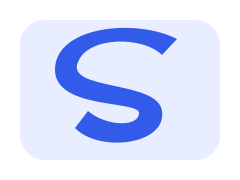

- Parameters used
- DXF R2000; source viewBox width 100 mm; flatness 0.1 mm.
- What this example does not prove
- Curves are approximated by line segments. Fills, color and stroke width are not CAD geometry; check the file in your target CAD tool.
Self-authored test artwork, processed by the product on 2026-11-19. Not customer work or a guarantee for other inputs. View reproducibility record
What this tool does
Turn supported 2D SVG geometry into DXF polylines for a CAD handoff. This is geometric conversion, not an image wrapper or a guarantee that a drawing is ready for manufacturing.
Input, output and limits
Static SVG up to 512 KB / 2,000 elements → DXF R2000. Up to 2,000 polylines / 20,000 vertices; curves flattened, unsupported text/use/clipping rejected.
Content reviewed: 2026-11-18 · Testing and known limits
How to use this tool
- 1
Open a static SVG made of paths and basic numeric-coordinate shapes.
- 2
Set drawing width, mm/in/unitless units and curve flatness; check unsupported content.
- 3
Convert, inspect open/closed polyline counts and download; reopen in your CAD software to verify scale.
Common questions
- Does SVG to DXF preserve curves as CAD splines?
- No. Curves and arcs are approximated as polyline segments; the flatness setting controls Bézier subdivision, not certified manufacturing error. The preview shows the emitted polyline geometry.
- How are SVG coordinates converted to drawing units?
- The source viewBox width maps to your chosen drawing width in mm, inches or unitless units. X is offset from the viewBox left; Y is flipped around its bottom. This avoids silently treating every SVG pixel as one millimeter.
- What happens to text, fills, strokes and clipping?
- Convert text to paths and expand use instances before input. Clipping, masks, patterns and nested SVG are rejected. Colors, opacity, fills and stroke thickness are not exported as CAD geometry; path centerlines and shape boundaries are exported.
- Is the DXF automatically safe for laser cutting or CNC?
- No. It preserves explicit path closure but does not weld gaps, union overlaps, offset kerfs or certify machine compatibility. Covered geometry can remain as separate outlines. Reopen in your target tool and check dimensions, duplicates and closed contours. Paths outside the SVG viewport are also exported; cropping the viewBox does not cut CAD geometry.
A tool for the next step
Create, refine and export your SVG.
Edit
Resize SVG
Set SVG width and height in pixels while preserving editable vector source. Lock the aspect ratio or explicitly stretch the drawing, then download SVG.
Crop SVG
Change the SVG viewBox to trim canvas space. Set the crop window or estimate visible bounds, preview the vector result and download locally.